27 June 2014

Fixing a Defective Drive Circuit in a Fender Hot Rod Deluxe

I just finished repairing another Fender Hot Rod Deluxe. A lot of problems that people have with this amp often somehow involve the Drive circuit and a couple of resistors that are prone to overheating (R78 and R79). The issue here was that the Clean and Drive channels both worked fine, but when the More Drive switch was engaged, there was no output and the LED turned off instead of turning red.

The first thing I noticed was that the amp had been worked on before, clearly because of the two aforementioned resistors. (If you're interested, this Premier Guitar article about the overheating resistor problem will bring you up to speed better than I can.) The first sign of previous work was that all of the bolts holding the circuit board to the chassis were missing. Oopsy. The only thing holding it in place is the board-mounted pots jacks, which are bound to fail eventually because of this. The second sign was the clearly non-original solder joints on R78 and R79. There was also hot glue or silicone under the resistors (Fig. 1a), which I don't think was stock in the 90s USA Hot Rod Deluxes (but I'm not positive about that). The back of the board all around those resistors was blackened as well (Fig. 1b), which I'm sure is the reason it was serviced.

Fig. 1a. Hot glue or silicone under R78 and R79

Fig. 1b. Blackened board and non-original solder beads on R78 and R79

After trying to figure out what had been done already, the first thing I checked was the solder joints on the Drive/More Drive LED (Fig. 2).

Fig. 2. The Drive/More Drive LED.

I looked at the joints and poked the leads (labeled R, C, and G in Fig. 2 above). G(reen) and C(ommon) were fine, which I expected, since the Drive channel worked fine, and when that's engaged, the LED is green. When I poked the red lead, I could see the tip wiggling loosely in the bad solder joint (circled in Fig. 3). Even without wiggling it, you can see that it's a bad joint. I touched that up and the amp worked fine.

Fig. 3. The culprit: a bad solder joint on the Drive/More Drive LED.
Most indicator lights have no effect on output, but in this amp, the LED is part of the Drive circuit. So if the LED isn't not functioning correctly, the Drive circuit isn't either. The LED's location in the circuit is outlined in red in Fig. 4.

Fig. 4. Unlike a lot of LEDs, the Drive/More Drive LED is part of the circuit, rather than just an indicator.
It doesn't take to much research to realize that this is not an isolated case of this particular LED causing issues with the Hot Rod Deluxe, so if you're having issues with the Drive channel, it's definitely worth a quick peek.


Line 6 Duoverb Head: Is Everything Glued?

I will start by admitting I was not successful at fixing this amp. I was pretty sure I wouldn't be, and I told my customer that I am not set up to diagnose or repair modeling amps or anything else that is mostly surface mounted components (which are tiny). But I said I'd take a look anyway. I always learn something, and this time was no exception, so I am sharing in case anyone else runs into the same problems I did.

To remove the chassis from the cab, I removed the four usual bolts—one near each corner of the top of the cabinet. The chassis didn't budge, so I removed the four bolts from the handle. That usually isn't necessary, but these handle bolts were indeed attached to the top of the chassis. The chassis still did not budge. There were no other bolts to remove, so after tugging a bit by hand and triple-checking that there were no other bolts, I got a putty knife and gently pried the chassis from the cabinet. That worked, and the reason it was so difficult to remove became apparent when I removed the chassis from the cabinet. In addition to the six bolts, it had been secured with a couple spots of glue.

I ran into a similar problem with the knobs. I didn't want to destroy any pots by pulling too hard on the knob, so I did a quick search to see if Line 6 also puts little dabs of glue on their knobs. I found a lot of forums saying that Line 6 knobs are difficult to get off, but none saying that they were glued, so I tried some pliers and a piece of plastic tubing to protect the finish (see Fig. 1 below). I put the tubing around the narrow part of the knob, gently rocked the knob back and forth a few times then pulled and they all came off with no problem.

Normally, when pot knobs are hard to remove, you would put something on the faceplate to protect it, then use a couple of small screwdrivers—one each side—to pry them off. However, most of these knobs were flush with the surface of the faceplate. I could have just fit a razor blade under them, but that would have damaged the surface.

So if you have the misfortune to work on one of these amps, the chassis does come out and the knobs do come off. Just be careful in both pursuits.

17 June 2014

Fixing the Reverb in a Mesa/Boogie Lonestar

This amp is one of the heaviest and by far the purplest that I have had the pleasure of fixing. It's so heavy (69 pounds, according to my bathroom scale) that I didn't even take it down to my workshop. I brought a bunch of tools up to the living room just to see if it was an easy fix. No sense lugging it for nothing, says I.

Fig. 1. Sixty-nine pounds of purple suede

I played through it for a a few minutes, of course, and the reverb was definitely on and turned up, but not audible. I tapped the tank and could hear the springs rattling around through the speaker, so the output side (black cable in Fig. 2) was good. I swapped the cable for some good ones and it still didn't work.

Fig. 2. The white cable is connected to the input jack on the reverb
tank, and the black cable is connected to the output. 

I took the cover off the reverb tank (it was mounted to a small piece of plywood), and immediately noticed a loose green wire (see Fig. 3). It was attached to the plastic connector that connects the input wire to the input transducer. I picked out the little bit of wire that broke off in the connector and reattached the wire.

Fig. 3. The culprit: a loose wire that somehow got disconnected from the plastic connector on the left.
(The cream-colored block under it is the input transducer)

I tested again, and it worked fine. I put everything back together and took my tools down to the workshop, which sure beat having to lug this beast.

11 June 2014

1964 Fender Blackface Super Reverb Repair

The latest bum amp in my workshop was a Fender Blackface Super Reverb, ca. 1964, which is quite possibly the heaviest amp I have ever carried. The Normal channel was fine, but the Vibrato channel had an intermittent volume drop, just enough to be noticeable.
Fig. 1. The Beast.

Fig. 2. This is why The Beast weighs 70 to 80 pounds.

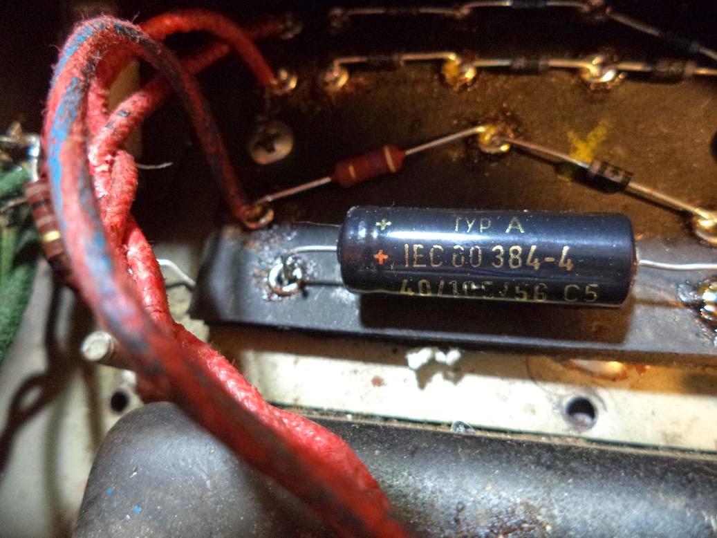
A visual inspection revealed a missing solder joint on the bias capacitor (see Fig. 3 below), which was not the cause of the problem, but certainly worth soldering.

Fig. 3. A conspicuous absence of solder.
I didn't see anything else untoward, so I did the chopstick test (with the amp on, poking each component with a chopstick). Still nothing. New tubes did not solve the problem either, so I did another chopstick test to no avail. I recorded all the voltages, but nothing jumped out as weird.

I started testing continuity among all the components and I found a cold solder joint on the board going to pin 1 on V5. I resoldered it, and the problem was gone. I took voltage readings again, and THEN the first measurement looked weird, even though it didn't jump out at me at the time. I guess I was too busy not electrocuting myself to notice the first time.

Both problems appear to have been the result of a recent recap job (I didn't do it) that was mostly good, but with a couple of iffy solder joints.