Showing posts with label Fender. Show all posts

10 January 2015

How to Install a Fender Blues Junior Bias Trimpot Without Drilling Holes in the Board

Where Fender Blues Junior mods are concerned, Bill M of billmaudio.com is truly a player on the world stage (see my previous appreciation of him and his mods here). The info and kits he provides on his site have been invaluable to me and countless others from around the world. So it is only with due respect (and sometimes awe) that I disagree with him on one issue: the need to drill holes in the board to mount a trimpot for bias adjustment.

His point is that bent leads on a trimpot may cause the pot to be wobbly, which in turn can cause the leads to break. First, the trimmer I used is not wobbly even with bent leads. Second, if you can use hot glue to secure other components on the board (electrolytic caps, multi-wire cables), you can use it here if you want. Again, there is no need to with the pot I used (but see my final note in the last paragraph). This is not the same pot that is included in Bill M kit (same specs, narrower housing), so I have included a close-up shot of it so you can find it. I got mine on eBay—a Bourns 3296 variable resistor, 50K ohm, 25-turn (Fig. 1).
 
Fig. 1. Here is the trimpot I installed in my Blues Junior. It is a little narrower than the one provided in Bill M's kits.
I recently installed this trimpot in my Blues Junior III (details vary among different BJr versions—check billmaudio.com for details). To avoid drilling a hole in the board (which I have done once before, and very nearly botched it), I bent the middle lead of the pot straight out and spliced a piece of wire to it (Fig. 2). I bent the outer leads slightly inward and down (note: you really only need to bend one lead, but I have an often unnecessary habit of centering things). I pressed the pot to the board and soldered it in place (Fig. 3).

Fig. 2. Ready to install: trimpot with extra wire spliced onto the middle lead and outer leads bent slightly inward

Fig. 3. Installed trimpot.
Because this trimpot housing has little nubs/standoffs on the edges (visible in my beautifully rendered and incredibly realistic diagram in Fig. 4 below), there is space underneath for the lead to fit between the housing and the board. As a result, when the trimpot is mounted, it is snug, not at all wobbly, and perhaps most important, reversible. Further, it was easy and not even remotely nerve-wracking.


Fig. 4. This is what a diagram looks like when it is created in Word and Paint. But you get the idea.
As a final note, though—and I can't stress this enough—I would personally take Blues Junior advice from Bill M before I took it from me. I am only sharing this as an alternative for people who aren't willing to drill a hole in the board. If that's a dealbreaker, this alternative might work for you.

27 June 2014

Fixing a Defective Drive Circuit in a Fender Hot Rod Deluxe

I just finished repairing another Fender Hot Rod Deluxe. A lot of problems that people have with this amp often somehow involve the Drive circuit and a couple of resistors that are prone to overheating (R78 and R79). The issue here was that the Clean and Drive channels both worked fine, but when the More Drive switch was engaged, there was no output and the LED turned off instead of turning red.

The first thing I noticed was that the amp had been worked on before, clearly because of the two aforementioned resistors. (If you're interested, this Premier Guitar article about the overheating resistor problem will bring you up to speed better than I can.) The first sign of previous work was that all of the bolts holding the circuit board to the chassis were missing. Oopsy. The only thing holding it in place is the board-mounted pots jacks, which are bound to fail eventually because of this. The second sign was the clearly non-original solder joints on R78 and R79. There was also hot glue or silicone under the resistors (Fig. 1a), which I don't think was stock in the 90s USA Hot Rod Deluxes (but I'm not positive about that). The back of the board all around those resistors was blackened as well (Fig. 1b), which I'm sure is the reason it was serviced.

Fig. 1a. Hot glue or silicone under R78 and R79

Fig. 1b. Blackened board and non-original solder beads on R78 and R79

After trying to figure out what had been done already, the first thing I checked was the solder joints on the Drive/More Drive LED (Fig. 2).

Fig. 2. The Drive/More Drive LED.

I looked at the joints and poked the leads (labeled R, C, and G in Fig. 2 above). G(reen) and C(ommon) were fine, which I expected, since the Drive channel worked fine, and when that's engaged, the LED is green. When I poked the red lead, I could see the tip wiggling loosely in the bad solder joint (circled in Fig. 3). Even without wiggling it, you can see that it's a bad joint. I touched that up and the amp worked fine.

Fig. 3. The culprit: a bad solder joint on the Drive/More Drive LED.
Most indicator lights have no effect on output, but in this amp, the LED is part of the Drive circuit. So if the LED isn't not functioning correctly, the Drive circuit isn't either. The LED's location in the circuit is outlined in red in Fig. 4.

Fig. 4. Unlike a lot of LEDs, the Drive/More Drive LED is part of the circuit, rather than just an indicator.
It doesn't take to much research to realize that this is not an isolated case of this particular LED causing issues with the Hot Rod Deluxe, so if you're having issues with the Drive channel, it's definitely worth a quick peek.


11 June 2014

1964 Fender Blackface Super Reverb Repair

The latest bum amp in my workshop was a Fender Blackface Super Reverb, ca. 1964, which is quite possibly the heaviest amp I have ever carried. The Normal channel was fine, but the Vibrato channel had an intermittent volume drop, just enough to be noticeable.
Fig. 1. The Beast.

Fig. 2. This is why The Beast weighs 70 to 80 pounds.

A visual inspection revealed a missing solder joint on the bias capacitor (see Fig. 3 below), which was not the cause of the problem, but certainly worth soldering.

Fig. 3. A conspicuous absence of solder.
I didn't see anything else untoward, so I did the chopstick test (with the amp on, poking each component with a chopstick). Still nothing. New tubes did not solve the problem either, so I did another chopstick test to no avail. I recorded all the voltages, but nothing jumped out as weird.

I started testing continuity among all the components and I found a cold solder joint on the board going to pin 1 on V5. I resoldered it, and the problem was gone. I took voltage readings again, and THEN the first measurement looked weird, even though it didn't jump out at me at the time. I guess I was too busy not electrocuting myself to notice the first time.

Both problems appear to have been the result of a recent recap job (I didn't do it) that was mostly good, but with a couple of iffy solder joints.

23 April 2014

The Bill M Mod Kit Saved my Blues Jr.

I was looking for a Blues Jr to mod and the cheapest one I found was $300 and it was already sold. The rest were $400 or more. Then I saw a Hot Rod Deluxe for $300, so I bought it because it was so cheap and I figured I could mod that. But it was way too loud to play at home and there weren’t too many interesting-sounding or necessary mods to do to it.

I put an ad on craigslist offering to trade it for a Blues Jr and someone responded. So now I have my Blues Jr.

It needed work. The input jack desperately needed to be replaced. The plastic threads were completely stripped and it wiggled a lot when you inserted or removed the cord. The footswitch input has the same problem (I haven't fixed that yet).

It sounded harsh and trebly. Ice picky, even. The highs were way too loud and the bass response was lacking. It was worthless for playing through. However, I wanted to learn more about the Blues Jr, so it was not worthless in that regard.

To fix these things, I ordered Bill M’s cream board mod for the Blues Jr. (first mod listed on his Mod Kits and Services page. My previous Blues Jr. was a 1995 green board, which sounded much better to me (especially after doing a couple of Bill M's mods to it, particularly the reverb fix). 

The first thing I did, even before removing the board is the Twin Stack mod (see Bill M's detailed instructions). I jumpered the two left lugs of the Mid control. It worked, but still not a fan of the sound. Even with the bass turned way up, it’s much too trebly and harsh.

This amp already had three new 22uF 450V caps, which must have been replaced as part of the repair that was done. R47 had previously burned out, leaving a substantial scorch mark on the PCB. It was replaced with a higher wattage resistor and placed away from the board an inch or so, presumably to keep it cooler. The 100uF  filter cap is still original, but that will be replaced with the Bill M mod. 

I considered the standby switches, but they seem to be unecessary, especially for how often I play. If I gigged regularly, I would have bought that as well. For the price and the ease of installation, it seems like a good investment.

I replaced the original GT EL84 power tubes, which were 10 years old or so, with a matched set of JJ EL84s for $30. I had some EHX 12AY7, 12AT7 tubes on hand, so I replaced V3 with the 12AY7 and V1 with 12AT7. The amp doesn't break up as quick, which suits me. The overdrive sounds okay, but still harsh.

Bill M's parts arrived pretty quickly. He has a notice on his website that it could take one to three weeks. I expected the worst, but was very pleasantly surprised. 

After removing the board (slow and steady wins the race here—see Bill M's instructions), I replaced the input jack and the Mid and Bass caps. Since I had the board out, I also redid the Twin Stack mod by placing a jumper on the solder side of the board. I didn't need to—having it on the component side of the board bugged me a little bit for some reason. Then I replaced a couple of other caps and jumpered another.

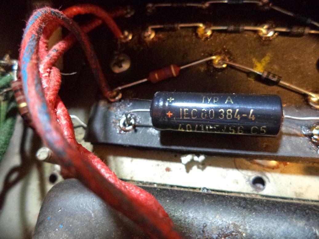
I replaced the 100uF filter cap and noticed that the three other 22uF filter caps were a mess. Well, I had noticed it before, but the mess that the previous repair left behind was really bugging me at this point. They used radial caps instead of axial and then flung hot glue on it. It looked awful (pic below), so I ordered three axial caps as well (from ebay, because I was in a real rush this time). 


There is also a big jumper installed behind the big resistor (previous repair job—pic below). It works, so I figure it's best not to mess with it.


I installed the bias trimpot. The drill bit was smaller than my drill would hold, so I used the smallest bit I had to start the hole, then finished with the bit included in the mod kit, rotating it with my fingers. Not perfect, but it worked out, fortunately.

I installed a small cap on R30 (reduces phase inverter oscillation—see Bill M's description). 

Finally, the 22uF caps came, and I installed them with no problems. 


I put everything back together, biased it per BillM’s instructions. Pretty easy, and I think it looks much better:

Here are the voltage readings on the power tubes, before and after the mod:
Tube Pin
JJ EL84 Before Mods
JJ EL84 After Mods
2 (Grid 1)
-10.5 V
-12.97 V
7 (Plate)
322 V
329 V
9 (Grid 2)
288 V
308 V

With a voltage drop of 2.4 V, I came up with 7.9-ish watts idle dissipation per tube, which will keep the tubes much cooler.

I put the back cover on and tried it. It sounds great. Bill M's mods turned what was to me an unusable amp into one that I now quite enjoy playing through. And a great thing about his mods is that he explains them. You don't just follow instructions and replace parts—he explains why you're replacing the parts. Thank you Bill M!