11 June 2014

1964 Fender Blackface Super Reverb Repair

The latest bum amp in my workshop was a Fender Blackface Super Reverb, ca. 1964, which is quite possibly the heaviest amp I have ever carried. The Normal channel was fine, but the Vibrato channel had an intermittent volume drop, just enough to be noticeable.
Fig. 1. The Beast.

Fig. 2. This is why The Beast weighs 70 to 80 pounds.

A visual inspection revealed a missing solder joint on the bias capacitor (see Fig. 3 below), which was not the cause of the problem, but certainly worth soldering.
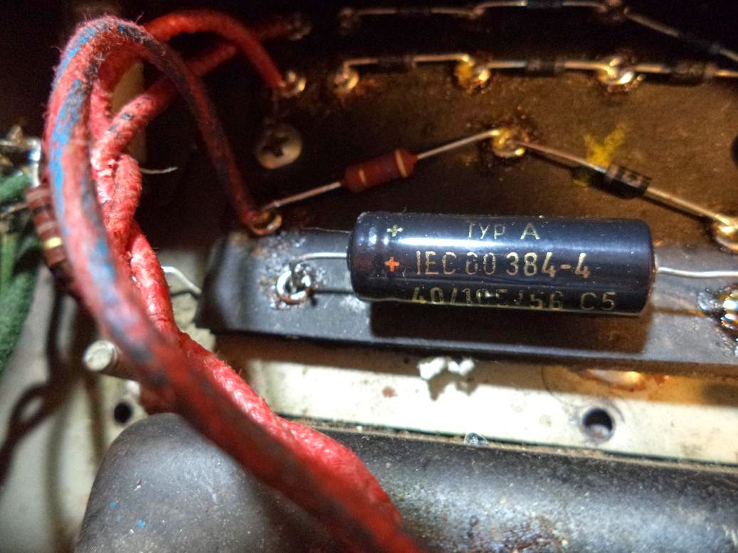
Fig. 3. A conspicuous absence of solder.
I didn't see anything else untoward, so I did the chopstick test (with the amp on, poking each component with a chopstick). Still nothing. New tubes did not solve the problem either, so I did another chopstick test to no avail. I recorded all the voltages, but nothing jumped out as weird.

I started testing continuity among all the components and I found a cold solder joint on the board going to pin 1 on V5. I resoldered it, and the problem was gone. I took voltage readings again, and THEN the first measurement looked weird, even though it didn't jump out at me at the time. I guess I was too busy not electrocuting myself to notice the first time.

Both problems appear to have been the result of a recent recap job (I didn't do it) that was mostly good, but with a couple of iffy solder joints.

27 May 2014

Marshall JCM 900 Dual Reverb Repair (No Presence Control)

My latest repair was a Marshall JCM 900 100 watt combo, which sounded great except that the Presence control did not have any apparent effect. A bad pot didn't make any sense. Usually, if a pot goes bad, there is some sort of funkiness, like scratchiness, odd dropouts, etc.

A visual inspection revealed nothing particularly noteworthy. I did notice that the two reverb pots had the back removed, pictured here:
Fig. 1. The backs had been removed on both reverb pots. Note the board version
on the left. You might need that when tracking down the correct schematic. 
Both were double gang pots, so removing the back only disabled the half that wasn't connected to the board anyway. That is worth noting only because the presence control (immediately next to the left reverb pot) was also a double gang, and one row of pins were snipped off so that they looked like they were connected to the board but were not.

I removed the board from the chassis by removing the knobs, the plastic nuts on the input and footswitch jacks, and finally the nuts on the Preamp (Ch. B) control and the Ch. B Reverb controls using a 10mm socket (pictured below).

Fig. 2. You'll need a 10mm socket for the nuts on the Preamp (Ch. B) control and the Ch. B Reverb pots
With the board out, the problem was quickly apparent. Someone had already worked on the Presence control and installed a jumper incorrectly, so that all pins went to ground regardless of the position of the control. I think the jumper was installed because it looks like the solder pad had lifted.

Fig. 3. I did not do this.
I would like to add that I did not put all of those scratch marks there. This work looks like it was done in the back of an offroad vehicle. Anyway, I removed that jumper and installed a longer jumper to the correct spot (C28), after which the Presence control worked fine.
Fig. 4. The new jumper. 
And here it is. Lovely.